Senin, 09 Maret 2015

UE4 Tools and Brushes

In this tutorial I will be showing you what tools and brushes are available to us in Unreal Engine 4 and what they are used for, giving you a basic understanding of what each does.


Tools and brushes in the modes panel.


Most of the tools and brushes can be found in the modes panel, which is located in the upper left corner of your screen.

BSP Brushes

Starting off in placement mode which is the first mode to the left. Here we can find the BSP brushes.
BSP brushes.
BSP brushes.
You can choose from a box, cone, cylinder, curved stair, linear stair, spiral stair and sphere BSP brushes. To use them you just click, drag and drop onto your level. BSP brushes can be used to create buildings and other objects in your game.
At the bottom of the panel on the BSP section you have the option to change the brush to add or subtract.

Paint

Paint.
Paint.
The paint tool can be used to paint your landscape, to paint texture onto static meshes and basic colours onto static meshes.

Landscape

Landscape.
Landscape.
In landscape mode, first of all you need to create your landscape. You can choose the size, change dimensions and basically make the landscape anyway you want. Then when you are happy with it click create. If you go wrong just click on the landscape on the view port and hit the delete key on your keyboard.


Editing and creating landscape options.
After creating you can now use the sculpt and paint tools in landscape mode.

Foliage

Foliage.
Foliage.

To use this you need to import a static mesh, something like grass, flowers or a tree.
You can download a good quality static mesh from the internet, then bring it into blender and delete all unnecessary objects which means everything but the actual mesh itself.

Mesh opened in blender.

 Make sure the materials are unpacked, you check this in the materials tab when you are clicked on the mesh. You can check this by clicking on the go to file, export, select .fbx and save.

New folder and import button.


Then in unreal engine, in the content browser (as seen in the image above), under game make a new folder called meshes and in this folder import your .fbx file.

Drag and drop area in foliage.


When you have that done simply click and drag the static mesh up to the modes panel in foliage.

After dragging and dropping the mesh into foliage.


Now you can edit the mesh you imported, by adding multiple texture and adding effects to the colour.

Geometry

Geometry.
Geometry.
In geometry editing mode you can edit objects in your level. Just click on the face of the object you want to edit and select witch feature you want to use. 


Baca selengkapnya

Jumat, 06 Maret 2015

How to create Pause Screen in UE4

Pause Screen in UE4
This image shows a finished Paused screen.

Step 1:

Before you open Unreal Engine go to www.dafont.com for download a font suitable for your game. One you download extract the file and installed ttf file. Copy the ttf file and paste in C:\Program Files(Program Files (x86))\Unreal Engine(Epic Games)\4.5(engine version)\Engine\Content\Slate\Fonts

After you have installed your font open Unreal Engine. In the Content Browser locate the folder “Game” and create new folder for User interface screens call it “UI”. In UI folder press right mouse bottom and select “User Interface” option then select “Widget Blueprint” in order to save press right click on widget blueprint and select save. Then double click on the widget blueprint to enter to edit menu.

This image show where you should create folder for User Interface.

This image shows where you should create Widget Blueprint.


Step 2:

On left top corner of the screen there is a folder called “Palette” expand “Common” select “Text Box” hold and drag on canvas or you can hold and drag on canvas under [Root] but make sure that you put on canvas.

This image shows Pause Screen editor.

This image shows canvas for screen.

Steps 3:

If you select text box then on the top right side of User Interface editor you can see “Details” options. Chose “Layout (Canvas Panel Slot) and press on Anchors and choose the middle. You can mess around and change “Style”, “Appearance” and other options. In “Content” option you can type the heading of your title.

This image shows options for Pause Screen.

This image show Text Block applied on canvas.
This image shows Text Block operation.

This image shows text applied on canvas.
This image shows colour options.
This image shows costumer font style. This is spot where you should put the font name that you want use.


Step 4:

You can add image if you want by dragging image box. To select image that you want to use and drag to “UI” folder. When your Pause screen is finished and you are happy of it than press Compile. Save and close the editor. You can find good image on http://www.freeimages.com/ .

This image shows an image box applied on canvas.


This image shows an image box applied on canvas.
The image that I chose is grunge border from http://vyawie.deviantart.com/art/Border-Black-Grunge-187744467 . You can search in Google Image for grunge border.

This image shows an image that I use for Paused Screen.

Step 5:

Select “Blueprints” then select “Open Level Blueprint”. Press right click and search for letter “P” to pause game and “X” to un paused game and add other important objects that will be needed for “Pause Screen” to work. Create new variable and select and then in variable type change to Boolean. Then create new Variable but this time change to Float.

This image show programmer for Paused screen.

This image shows the program for Paused screen.

Step 6:

If you finish coding press compile and save your Pause screen and you can exit programming. The last thing that is left to test if pause screen is working is to “x” out of programming editor and see if it works.

This image shows a finished Game Paused screen.
You can also watch a video tutorial about how to create a Pause Screen.


Baca selengkapnya

How to make a Start Screen for UE4

Start Screen for UE4
The Completed Start Screen

This tutorial will go through how to create a Start/Main Menu for a game on Unreal Engine. In a previous tutorial we showed that when setting up a level on Unreal Engine, for settings we added With Starter Content.

Starter Content
Starter Content

Getting Started

The first thing you do go to your user interface folder in the Content Browser. When you click into the folder and then right click on a black space anywhere in the folder. A tool bar will then appear. Scroll down and click on the User Interface bar and then select the Widget Blueprints sub bar.  A new widget file will appear and you then name it, for example Start_Screen. You then save it.

Content Browser
UI Folder

Design

With your new User Interface file, you click into it which brings you into widget editor. We will be making the buttons and background image with the designer.

Widget Editor
Widget Editor

Palette
Palette
You first select Button on the Palette. To place it onto the screen. Note: if anything is unable to be dragged onto the screen, you can still drag it onto the Hierarchy, onto the Canvas Panel, it will still appear. A Details Panel will show like in the Level Editor where you can fix anchor points, positioning etc. 

Details
Button Details


Button
Button
Hierachy
Hierarchy


After you place your buttons onto the screen, you bring in a text block for each of your buttons.For the Text that you're going to use for your title and your buttons, have a custom font installed, and have it looking suitable to your game.
Text Block
Text Block
You use the Details Panel to make the colour, font and text content. 

Text Details
Text Details
So for each button we need to give each a name and a background colour. So for this we will name our buttons START and QUIT. 


Buttons
Menu Buttons

After you have your buttons made, bring in your background image. The image that we use is was imported into the UI folder in the Content Browser. From the Palette, drag on IMAGE. In the Details Panel, in Appearances, click into Brush. Here you can select the image you have imported by searching for it. When you have your image, adjust its size so it fills as a background screen.

Image Details
Image Details
Background Image
Background Image


When you have made your background screen, add in another text block to give your add your game name. 
Game Title
Title

Blueprints


After you have your Menu designed, click onto the Blueprints and click on, Open Level Blueprints.

Blueprints Buttton
Blueprints Button
These are the codes for your menu...

Blueprints
Menu Blueprints
After that is done, press play to test out your menu. It should look something like the image below.


Finished Screen
Finished Screen


Baca selengkapnya

Creating A Speed Pick Up in UE4

Speed Pick Up in UE4
This is the pick up that we will be making
In this tutorial we will be creating a pick up that, rotates, hovers, and (once collected) increases your character's speed.

Step 1: Creating a New Blueprint

The first thing that we need to do is create a new blueprint, to do this in the content browser, open the blueprints folder then right click on an empty space and select blue print from the pop up menu.

This picture shows where I have a pick up.

This tutorial is being made in UE4s latest version.
When you select Blueprint, this window will pop up. from here we want to select actor.

From this we select actor.

Step 2: Creating the Collision

Now that we have our actor created double click on the thumbnail, this will open the editor for that blueprint.

This is the blue print editor for the blueprint we created.

In here we need to add a collision, so in the top right, it will say '+Add Component'. Click this and select sphere collision, if you are using an older version of UE4 you can select a sphere. I named mine collision once brought in.

This is the sphere collision.

Now that we have this created, we need to add a static mesh, to do this we need to be able to see both the blue print editor and the props folder in the starter content. Im going to select the material sphere and drag it into the blueprint editor and drop it in the grey space under the add component section.

This is the material sphere in the blueprint editor.

As we can see from the above picture the sphere has swallowed our collision. So im going to use the scale widget to scale my material sphere down. To do this, select the ball, press the space key twice, the widget you are looking for looks like this,

Scale Widget

What Im going to do to scale the ball so it doesnt become an egg, select one of the arrows, click and drag one step, once you use the widget you will see what I mean. Start with the green arrow and work around, scaling down one at a time until the collision resurfaces over the sphere.

The scaled down version.
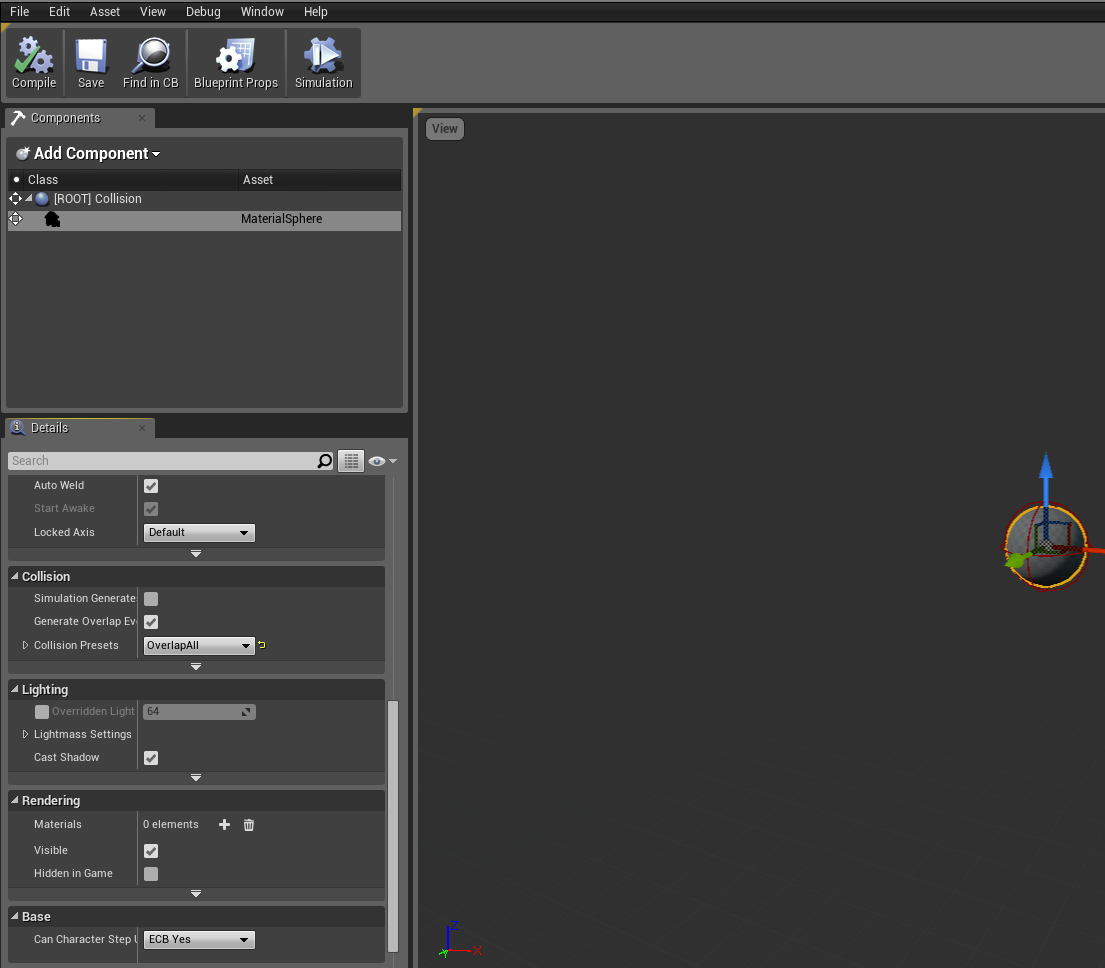
We need to change the presets of the ball to Overlap all. Scroll down the menu on the left handside, for the collision and the mesh. You will see the Blockall Dynamic, change this to overlap all.

I have the options changed on the left of the screen.

From the picture below select the event graph option so that we can start our blueprints coding.
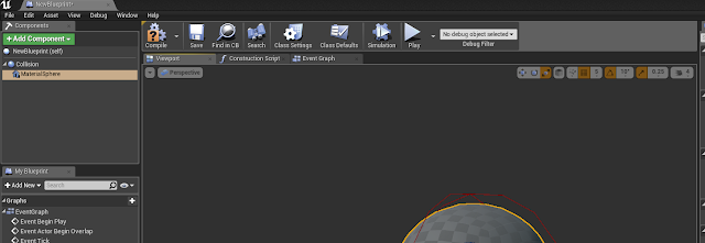
Event graph is the third tab above the sphere.


Step 3: Blueprints for rotation

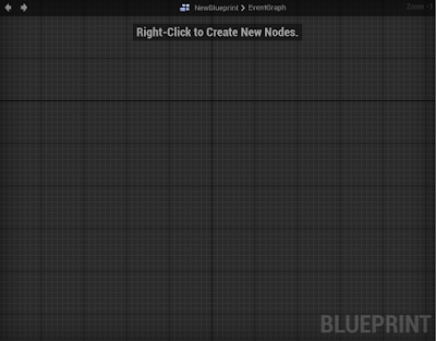
When your in the event graph this is how it should look.
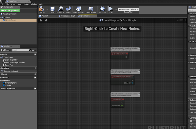
Older versions will have different organised details panels.

Ive just deleted all of the coding to start fresh.

The next thing that we do is right click on the grid, and search for event tick once this has been added, select the material sphere in the top right hand panel, then right click, open add event section, then select the collision drop down option, and from there select begin overlap.
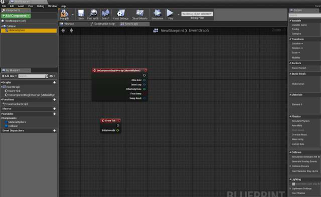
The beginnings of the coding.
Right click on the grid again, this time type 'actor location' into the search bar, select the green option that says, 'get actor location'.
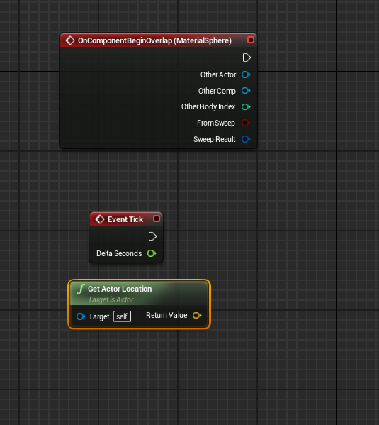
This is the added get actor location code.

We are going to start making the pick up rotate, the first thing I did was move the event tick above the begin overlap. From the white arrow, drag out and when you release you have the option to search, look for 'local rotation'. The newer version will give you the option to apply the rotation to either the material sphere or the collision, we want to select the material sphere version. In the older versions of the programme you don't need to worry about what to select.
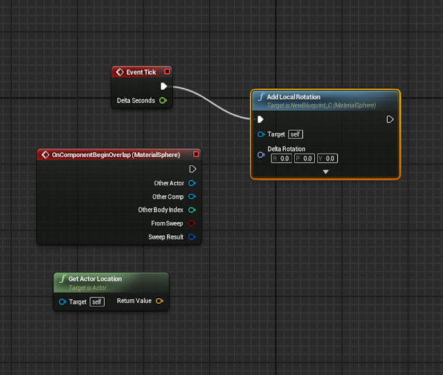
Once we have selected the node to add it is then connected.

The next thing that we will add is an emitter, for this I dragged from the white arrow on the begin overlap node, in the search bar I typed 'emitter', from the options you want to select spawn emitter at location.

In the newly added node, under the emitter template drop down, select the explosion option.
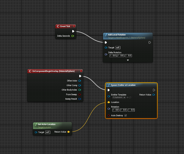
Then we connect the green node into the location.

The next pieces of code we are going to add are brought out from the begin overlap node, in this node select the blue other actor circle, drag this out and type 'cast character' select my character from the options. Once this has been added hit save, just to be safe.

Then from the cast character node drag out the blue circle and search for character movement, you need to scroll down to the bottom of the results in order to find the 'Variables' section, there will only be one option here and that is the one that we want.
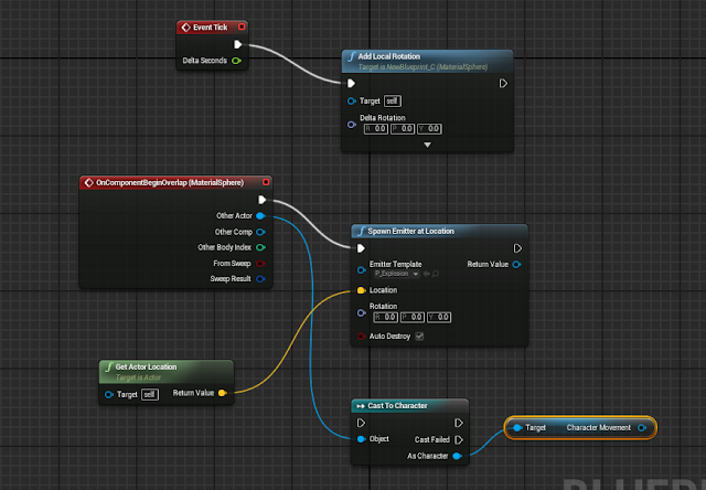
We are nearing the completion of our coding.

This time we will add three pieces of coding that will complete the coding that we need to gather in order to create the floating pick up, for now will we just grab it all and put it into the grid.. 
First thing to do is right click, from the pop up scroll down to the bottom and select the timeline option, name this blueprint.

The second piece is right click, followed by a search for 'local offset' add this beside the timeline.
The last piece we are going to add in this section is a destroy actor node, right click search destroy actor and add this into the grid.
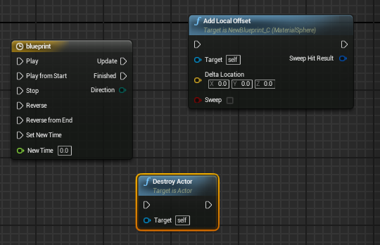
We will connect this in the next step.

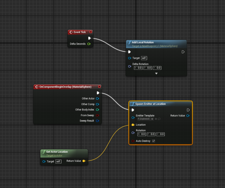
The last piece of coding that needs to be added is a 'set max walk speed' node. Drag out from the character movement reference, right click and search walk speed, you may need to turn off the context sensitive option in order to find it, select the node that says 'set max walk speed'. Once you have added this piece of code, change the value to 1500, then connect all of the coding up as you see below.
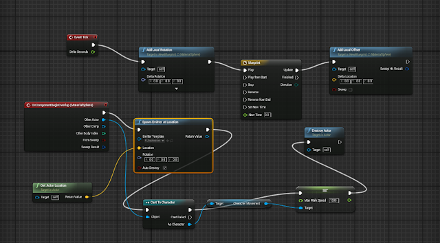
This is the coding complete for now. The walk speed value is now 1500.


Step 4: Creating the up/ down motion on our pick up


To add this select the timeline node in the blueprint and double click, this is the window that you will see, when this opens select the V option to add a vector track.
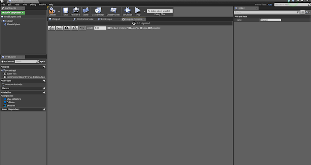
The Vector track is how we will create the bop effect.

This image below shows how our window will look once we have applied the vector track.
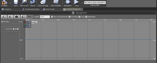
Added Vector Track.

Step 5: Adding Key Frames to a Vector Track

We are going to be adding our key frames on the Z axis, because we want our ball to go up and down in the air.

To do this we need to click the lock symbol beside the green, and red boxes in the top corner of our vector track, this will only leave the Z axis available to work on.
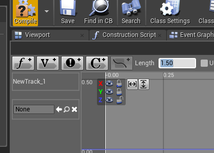
The x, y axis is locked and have the length set 1.50.
To add a key frame we go to the start of the animation on the blue line, where it says 0.00 hold down the shift key and left click in order to add a keyframe.

This will bring up some options seen below.
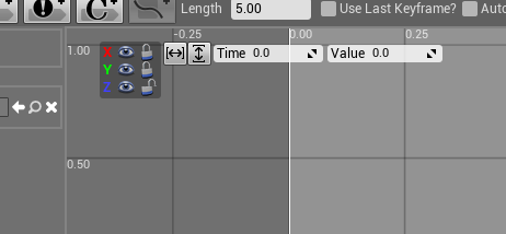
Set both values to 0.00.
Next we make sure to have the Z axis only unlocked, and we do another key frame, this time at the 0.50 point. the values this time are .5 and .5.
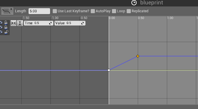
Second key frame added.

The next key frame will be added at the 1.00 mark. The values this time will be 1.00 and then -0.05.
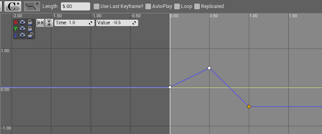
Third key frame creating motion.

The final key frame will be added at the 1.50 mark, the values this time are 1.50 followed by 0.00. We are also going to need to tick the loop option. Dont forget to compile and save.
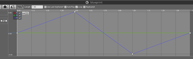
Here we also change the length to 1.50.
Now we can go back to the graph, we now have an extra option on our timeline node and this needs to be connected.
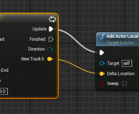
Connect the yellow into the yellow and compile/ save.

Now that everything is connected and complied we can play and try it out. The orb will bounce up and down whilst rotating and will allow our character to increase their speed by hitting it.


Step 6: Adding a material to the pick up

To add a material to the sphere we open the sphere in the blueprints folder. 
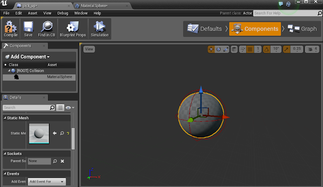
The sphere is selected in the blueprints editor.
From here if you look at the above picture you can see, on the left hand side of the screen, static mesh, double click on this thumbnail image and it will open up a new window that looks like this.

This is the editor for the sphere.
All we need to do now is drag a material from the content browser onto the section on the right hand side that has the ball in it, this will apply the material and then you can hit save.

This is the texture I chose for my pick up.
This concludes the tutorial. When you hit play you will have a fancy functional pick up.


Baca selengkapnya